
These constraints specify clock related definitions which affect
synthesis and timing analysis.
create_clock:
create_clock -period period_value [-name clock_name] [-waveform edge_list] [-add] [source_objects]
# Defines a clock. When clock_name is not specified, the clock name is the name
of the first source object. The -period
option specifies the clock period. The -add option is used to create a clock at a pin that already has an
existing clock definition. Else if this option is not used, this clock
definition overrides any other existing clock definition at that node. The -waveform option specifies the rising edge and
# falling edge (duty cycle) of the clock. The default is (0, period/2). If a clock definition is on a path
# after another clock, then it blocks the previous clock from that
point onwards.

Examples:
create_clock -period 20 -waveform {0 6} -name SYS_CLK [get_ports
SYS_CLK]
# Creates a clock of period. 20ns with rising edge at 0ns and the
falling edge at 6ns.
create_clock -name CPU_CLK -period
2.33 -add [get_ports
CPU_CLK]
# Adds the clock definition to the port without overriding any
existing clock definitions.
create_clock -period 4.75 clock
#Clock period constraint set at 4.75 (210
MHz).
create_generated_clock:
create_generated_clock [-name clock_name] -source master_pin
[-edges
edge_list] [-divide_by factor] [-multiply_by factor] [-duty_cycle percent] [-invert] [-edge_shift shift_list] [-add] [-master_clock clock] [-combinational] source_objects
# Defines an internally generated clock. If no
-name is specified, the clock name is that of the first source object. The
source of the generated clock, specified by -source, is a pin
or port in the design. If more than one clock feeds the source node, the -master_clock option must be used to specify which of these
clocks to use as the source of the generated clock. The -divide_by option can be used to specify the clock division
factor; similarly for -multiply_by. The -duty_cycle can
be used to specify the new duty cycle for clock multiplication. The -invert option can be specified if the phase of the clock has been
inverted. Instead of using clock multiplication or division, clock generation
can also be specified using –edges
and -edge_shift options.
The -edges option specifies a list of three numbers specifying the edges of
the master clock edges to use for the
first rising edge, the next falling edge, and the next rising edge. For
example, a clock divider can be specified as -divide_by 2
or as -edges {1 3 5}. The -edge_shift
option can be used in conjunction with the -edges option to specify an amount to shift for each of the three edges.

Examples:
create_generated_clock
-divide_by
2 -source [get_ports sys_clk] -name
gen_sys_clk [get_pins UFF/Q]
create_generated_clock -add -invert
-edges
{1 2 8} -source [get_ports mclk] -name
gen_clk_div
create_generated_clock -multiply_by
3 -source [get_ports
ref_clk] -master_clock clk10MHz
\
[get_pins UPLL/CLKOUT] -name gen_pll_clk
set_clock_latency:
Estimated clock insertion delay is modeled using this constraint.
This is used at synthesis stage and prelayout timing analysis. After CTS this is
replaced by real propagated clock latency.

set_clock_latency [-rise] [-fall] [-min] [-max] [-source] [-late] [-early] [-clock clock_list] delay
object_list
# Specifies the clock latency for a given
clock. There are two types of latency: network and source. Source latency is the clock network delay between the clock
definition pin and its source, while network latency
is the clock network delay between the clock definition
pin and the flip-flop clock pins.
Examples:
set_clock_latency 1.86 [get_clocks
clk250]
set_clock_latency -source -late
-rise
2.5 \
[get_clocks
MCLK]
set_clock_latency -source -late
-fall
2.3 \
[get_clocks
MCLK]
set_clock_latency 0.45 clock
#This
provides possible network latency constraint to DC.
set_clock_latency –source 0.4 clock
set_clock_latency –source 0.4 clock
#Source
latency of 0.45 is selected.
set_clock_uncertainty:
This constraint models clock skew affects on the clock. This is
used to ass a certain amount of margin to the clock. After CTS real propagated
skew is considered.

set_clock_uncertainty [-from
from_clock] [-rise_from rise_from_clock] [-fall_from fall_from_clock] [-to to_clock] [-rise_to rise_to_clock] [-fall_to fall_to_clock] [-rise] [-fall] [-setup] [-hold] uncertainty [object_list]
# Specifies the clock uncertainty for clocks
or for clock-to-clock transfers. The setup uncertainty is subtracted from the
data required time for a path, and the hold uncertainty is added to the data
required time for each path.
Examples:
set_clock_uncertainty -setup -rise
-fall
0.2 [get_clocks CLK2]
set_clock_uncertainty -from [get_clocks
HSCLK] -to [get_clocks SYSCLK] -hold 0.35
set_clock_uncertainty –setup 0.475 clock
# -ve clock skew can
lead to setup violations. Possible value of –ve skew is provided to DC so that
it can model for that. Generally setup uncertainty is taken as 10% of the
clock.
set_clock_uncertainty –hold 0.27 clock
set_clock_uncertainty –hold 0.27 clock
# +ve clock skew can
lead to hold violations. Possible value of +ve skew is provided to DC so that
it can model for that. Generally hold uncertainty is taken as 5% of the clock.
set_clock_transition:
set_clock_transition:
set_clock_transition [-rise] [-fall] [-min] [-max] transition
clock_list
# Specifies the clock transition at the clock definition point.

Examples:
set_clock_transition -min 0.5 [get_clocks SERDES_CLK]
set_clock_transition
-max
1.5 [get_clocks SERDES_CLK]
set_clock_transition 0.04 clock
#Clock
transition time of 0.04 is modeled.
Other Clock Constraints:
set_clock_gating_check [-setup setup_value] [-hold hold_value] [-rise] [-fall] [-high] [-low] [object_list]
# Provides the ability to specify a clock
gating check on any object. Clock gating checks are performed only on gates
that get a clock signal. By default, the setup and hold values are 0.
Examples:
set_clock_gating_check -setup 0.15 -hold 0.05 [get_clocks ck20m]
set_clock_gating_check -hold 0.3 [get_cells U0/clk_divider/UAND1]
set_clock_groups [-name name] [-logically_exclusive] [-physically_exclusive] [-asynchronous] [-allow_paths] -group clock_list
# Specifies a group of clocks with the specific property and
assigns a name to the group.
set_clock_sense [-positive] [-negative] [-pulse pulse] [-stop_propagation] [-clock clock_list] pin_list
# Set clock property on pin.
set_input_delay:
set_input_delay [-clock clock_name] [-clock_fall] [-rise] [-fall] [-max] [-min] [-add_delay] [-network_latency_included] [-source_latency_included] delay_value
port_pin_list
# Specifies the data arrival times at the
specified input ports relative to the clock specified. The default is the
rising edge of clock. The -add_delay
option allows the capability to add more than
one constraint to that particular pin or port. Multiple input delays with
respect to different clocks can be specified using this -add_delay option. By default, the clock source latency
of the launch clock is added to the input delay value, but when the -source_latency_included option is specified, the source network
latency is not added because it is assumed to be factored into the input delay
value. The -max delay is used for clock setup checks and recovery checks, while the
-min delay is used for hold and removal checks. If only -min or -max or neither is specified, the same value is
used for both.

Examples:
set_input_delay -clock SYSCLK 1.1 [get_ports MDIO*]
set_input_delay
-clock
virtual_mclk 2.5 [all_inputs]
set_input_delay 0.40 [all_inputs]
#Input
delay of 0.4 is set to all inputs.
set_output_delay:
set_output_delay [-clock clock_name] [-clock_fall] [-level_sensitive] [-rise] [-fall] [-max] [-min] [-add_delay] [-network_delay_included] [-source_latency_included] delay_value
port_pin_list
#
Specifies the required time Specifies the required time of the output relative to
the clock. The rising edge is default. By default, the clock source latency is
added to the output delay value but when the -source_latency_included option is specified, the clock latency value is not added as it is
assumed to be included in the output delay value. The -add_delay option can be used to specify multiple set_output_delay on a pin/port.

set_output_delay 0.40 [all_outputs]
#Output
delay of 0.4 is provided. If all outputs are registered this delay does not
affect the timing analysis.
Timing Exceptions:
set_false_path:
set_false_path [-setup] [-hold] [-rise] [-fall] [-from from_list] [-to to_list] [-through through_list] [-rise_from rise_from_list] [-rise_to rise_to_list] [-rise_through -rise_through_list] [-fall_from fall_from_list] [-fall_to fall_to_list] [-fall_through fall_through_list]
# Specifies a path exception that is not to be considered for STA.

Examples:
set_false_path -from [get_clocks
jtag_clk]
-to [get_clocks
sys_clk]
set_false_path
-through
U1/A -through U4/ZN
set_multicycle_path:
set_multicycle_path [-setup] [-hold] [-rise] [-fall] [-start] [-end] [-from from_list] [-to to_list] [-through through_list] [-rise_from rise_from_list] [-rise_to rise_to_list] [-rise_through rise_through_list] [-fall_from
fall_from_list] [-fall_to fall_to_list] [-fall_through fall_through_list] path_multiplier
# Specifies a path as a multicycle path.
Multiple –through can also be specified. Use the -setup option if the multicycle path is just for setup. Use the -hold option if the multicycle path is for hold. If neither -setup nor -hold
is specified, the default is -setup and the default hold multiplier is 0. The -start refers to the path multiplier being applied to the launch clock,
while -end refers to the path multiplier being applied to the capture clock. Default
is -start. The value of the -hold
multiplier represents the number of clock
edges away from the default hold multicycle value which is 0.
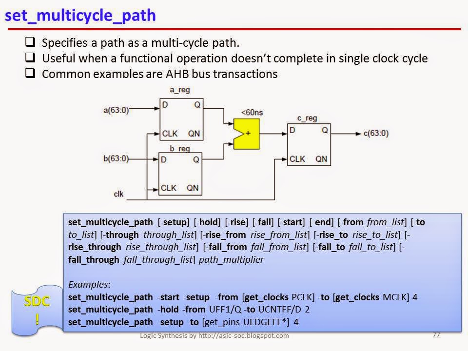
Examples:
set_multicycle_path -start -setup
-from [get_clocks
PCLK] -to [get_clocks MCLK] 4
set_multicycle_path -hold -from
UFF1/Q -to UCNTFF/D 2
set_multicycle_path -setup -to
[get_pins UEDGEFF*] 4
set_max_delay:
set_max_delay [-rise] [-fall] [-from from_list] [-to to_list] [-through through_list] [-rise_from rise_from_list] [-rise_to rise_to_list] [-rise_through rise_through_list] [-fall_from
fall_from_list] [-fall_to fall_to_list] [-fall_through fall_through_list] delay_value
# Sets the maximum delay on the specified path. This is used to
specify delay between two arbitrary pins
# instead of from a flip-flop to another flip-flop.

Examples:
set_max_delay -from [get_clocks
FIFOCLK] -to [get_clocks MAINCLK] 3.5
set_max_delay -from [all_inputs] -to [get_cells UCKDIV/UFF1/D] 2.66
Note: I have extensively referred [BH] for this article.
References
[HM] Himanshu Bhatnagar, Advanced ASIC chip Synthesis Using Synopsys Design Compiler, Physical Compiler and PrimeTime, Kluwer Academic Publishers, Second edition, 2002
[DC] Design Compiler® User Guide, Version X-2005.09, September 2005
[HM] Himanshu Bhatnagar, Advanced ASIC chip Synthesis Using Synopsys Design Compiler, Physical Compiler and PrimeTime, Kluwer Academic Publishers, Second edition, 2002
[DC] Design Compiler® User Guide, Version X-2005.09, September 2005
[RC] Using Encounter® RTL Compiler, Product Version 8.1.202, April 2009
[BH] J. Bhasker,
Rakesh Chadha, Static Timing Analysis
for Nanometer Designs A Practical Approach, 2009
very nice
ReplyDeleteSpank me. It’s the only way I learn. Hey, i am looking for an online sexual partner ;) Click on my boobs if you are interested (. )( .)
ReplyDeleteJoin VLSI Professional Certification Training with Internship at #GoldenLightSolutions
ReplyDeleteInternship by one of the most reputed VLSI service design company.
Exposure to work on live industrial and R&D project.
Mentorship by leading technology leaders.
login to www.goldenlightsolutions.com
It is a very informative and useful post thanks it is good material to read this post increases my knowledge. Web design jaipur
ReplyDeleteWell, place for shopping wall clock decor for decoration home and improvement office, house, university and kitchen. for more detail click now @
ReplyDeletewall clock decor
what is the duty cycle of a clock generated by SDC command create_generated_clock if master clock has 30% duty cycle and generated clock is -divided_by 2 ?
ReplyDelete